Streymalvi features
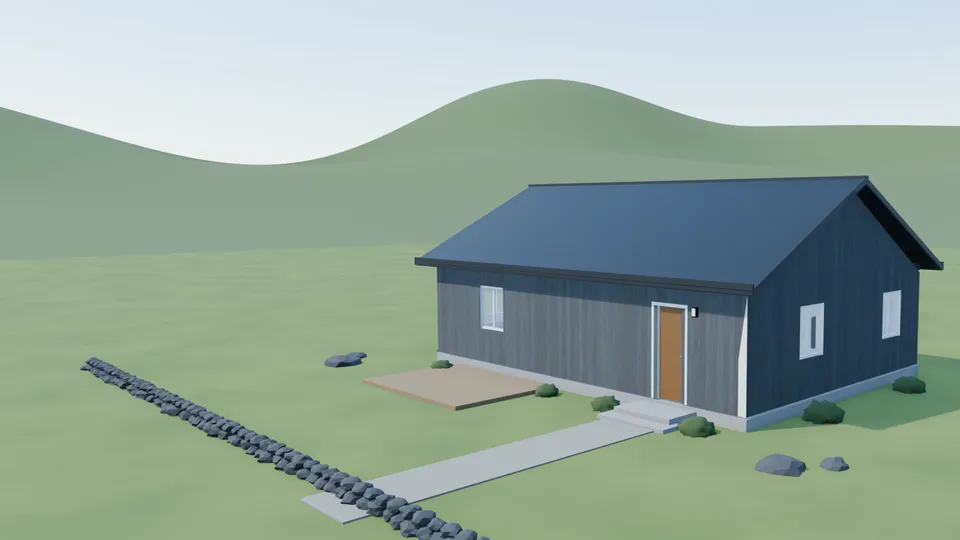
01 Building Design
From Sketch to Structure
Draw walls, rooms, doors and windows in the Building Planner, add dimensions, and look at the same model in 3D.
- Straight walls with joins and mitred corners
- Rooms with automatically computed areas
- Doors and windows as real openings in the walls
- Dimensions, a measuring tool, floors and stairs
Explore Building Design
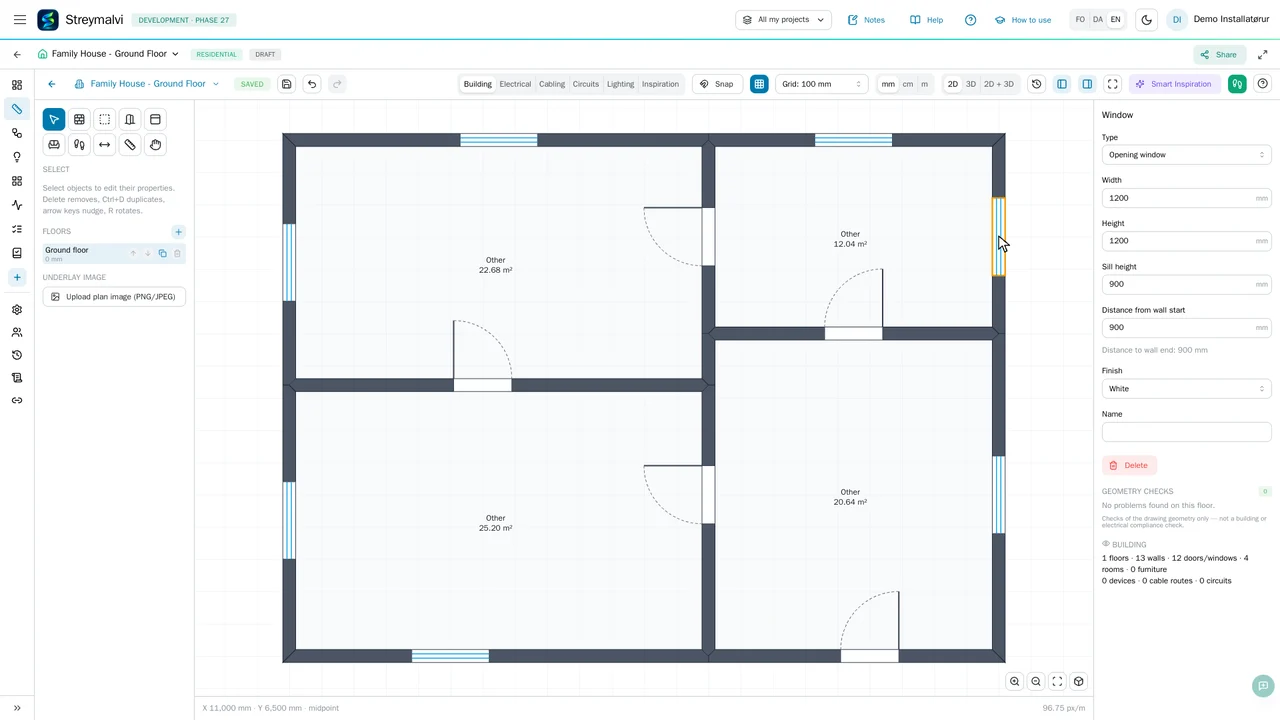
The building model is shared with the rest of the project. Electrical devices placed later stay attached to their walls and follow every edit. The 3D view offers orbit, top and interior presets, a cutaway and soft shadows.
About this clip. The first three seconds are the real Building Planner, sped up. The rising walls, the roof and the landscape are a cinematic rendering of the same house: in the app the 2D and 3D views switch instantly, and roofs are not modelled.

02 Electrical Installation
Design. Connect. Test.
Place sockets, switches and ceiling lights on the plan, group them into circuits on the distribution board, and check how each switch drives its luminaire in the simulation.
- Devices follow the walls when the building changes
- Circuits, cable routes and length estimates
- Auto-Route and Auto-Wire proposals you confirm
- Load, cable sizing, voltage drop and fault current calculations
Explore Electrical Installation
E1 off. Circuit C01 de-energised.
Illustration on this page. In Streymalvi the same switch-to-luminaire behaviour runs in the residential simulation, labelled Simulation only.
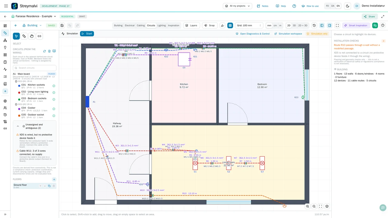
About this clip. Device placement and Circuits mode are real captures. The coloured routes on the Family House reconstruct the app's route display, and the switch turning on the light recreates the simulation behaviour. No electrical measurement is shown or claimed.

03 Interactive Walkthrough
Step Inside Your Design
Walk through the house you designed at eye height, move from room to room and operate the switches while the simulation runs.
- First-person movement with keyboard controls
- Room labels and walkable stairs
- Switches and smart-home logic respond in the simulation
Explore the Walkthrough
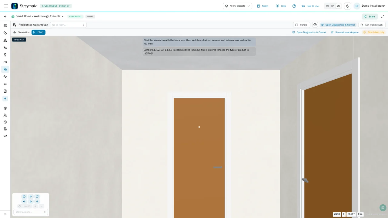
Status and clip notes. The residential walkthrough is marked partial in v0.27.6. The opening of the clip is the app's 3D view; the walk and the switch press are a Blender recreation at 1.62 m eye height, because no capture of a switch press exists.
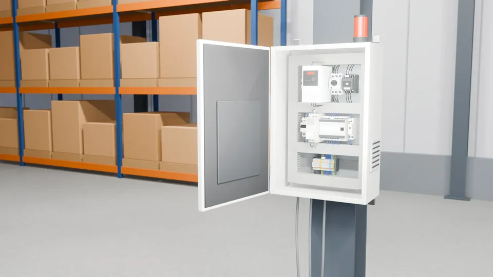
04 Electrical Engineering
From Schematic to Hardware
Draw the circuit on multi-page sheets, then let Streymalvi propose the cabinet: components, their arrangement on the DIN rails and the wiring come from the schematic, and you decide what to apply.
- 45 built-in IEC 60617-style symbols with cross-references
- Generate components, arrangement and wiring as previewed proposals
- Duct routing, wire numbering and lengths
- 3D cabinet view with a hinged door and real catalogue products
Explore Electrical Engineering
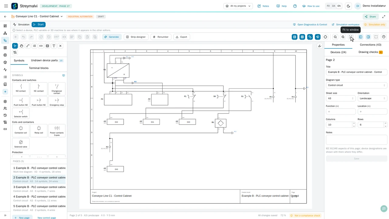
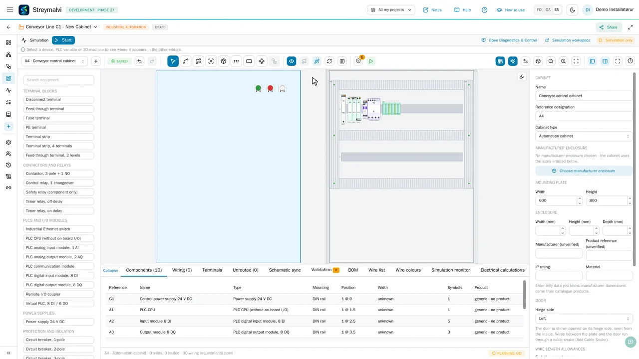
About this clip. The first 3.5 seconds show the real schematic pages. The symbols flying onto the mounting plate dramatise the real Generate → Components from the schematic → Apply workflow, which the app shows as a 2D placement preview.

05 PLC & Automation
Program. Simulate. Solve.
The stop gate holds and the boxes pile up. One contact in the ladder program was written normally open instead of normally closed. Stop the simulation, change it to NC, start again, and the queue clears.
- Ladder with live power-flow monitoring
- Diagnostics & Control: force and release I/O, every action audited
- Step one scan cycle at a time
- 3D factory with conveyors, gates and sensors on the same simulation
Explore PLC & Automation
NO contact stays open while the outfeed is clear: GT_Release is off, the gate holds and the queue grows.
Illustration on this page, simplified from the conveyor example in the film. In Streymalvi you change the contact in Properties → Type with the simulation stopped; power flow is shown in green while it runs.
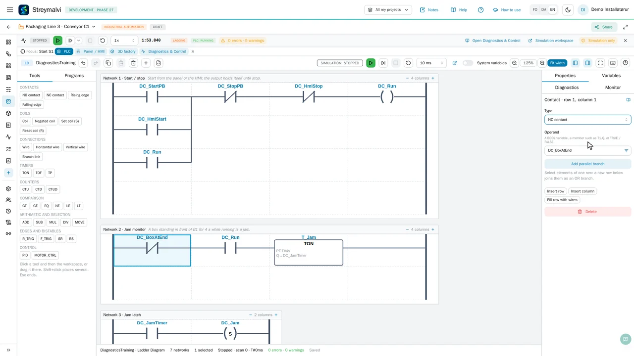
About this clip. The conveyor and the gate run from a simulation baked from the PLC logic. The right-click menu entry Edit program is a reconstruction: in v0.27.6 the program is opened through the Focus chips or the PLC tab. The ladder is re-drawn in the editor's style, the warning beacon is cinematic, and the NO → NC change is a real editor capability.

06 Thermal Analysis
Understand the Heat
Thermal analysis reads the power loss of every device in the cabinet and calculates the air temperature inside, how fast it warms up, and how much heat has to be removed.
- Steady state, heating, cooling and condensation
- Transient simulation with duty cycles
- Animated 2D heat map of the mounting plate
- Saved analyses and a thermal report
Explore Thermal Analysis
Steady state: Tin = Tamb + P / (k · Aeff)
48.3 °C cabinet air · about 23 W to remove for a 40 °C target
Illustration of the documented steady-state method for the 600 × 400 × 200 mm cabinet in the clip (k = 4.75 W/m²K, Aeff = 0.584 m²). It is not a sizing tool. In Streymalvi, unknown device losses make a result a lower bound, and nothing is presented as a compliance check.
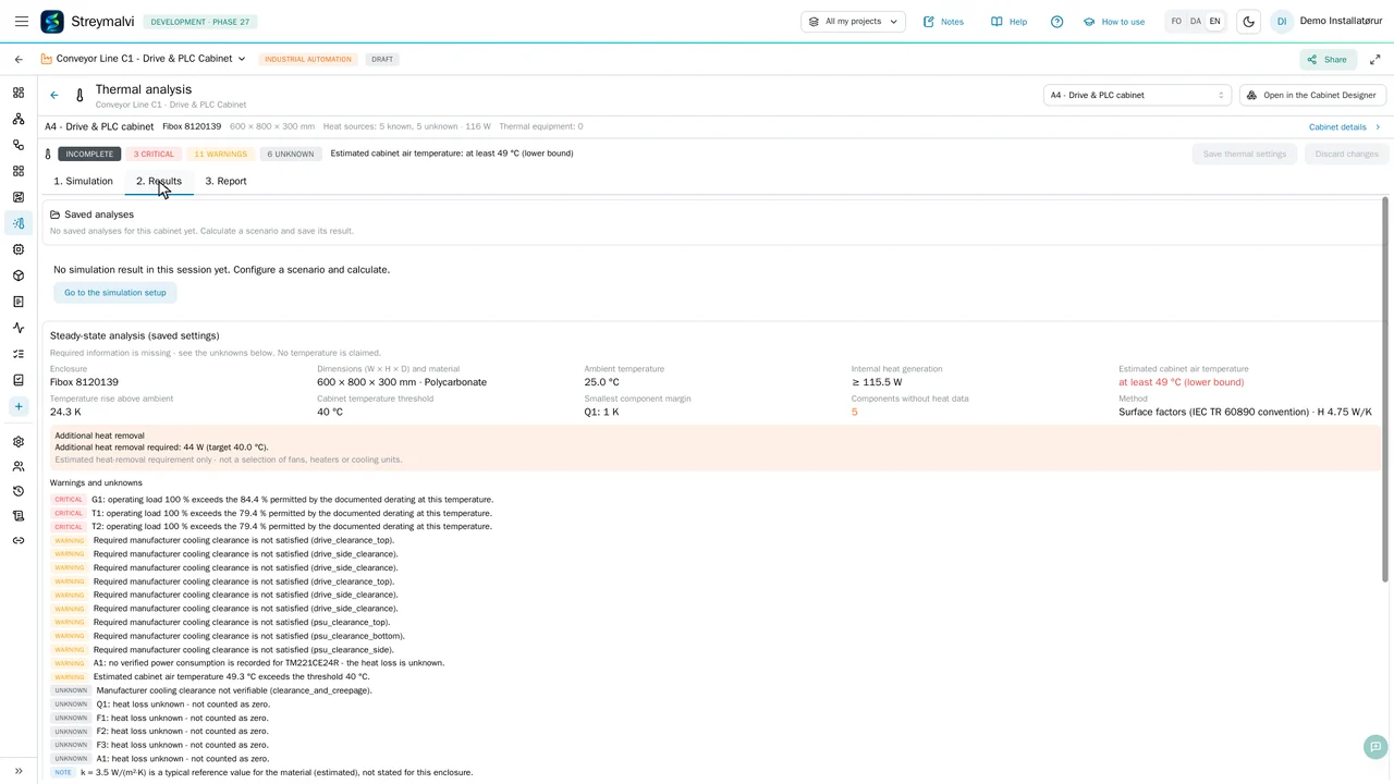
About this clip. The heat maps are calculated with the app's documented method from typical datasheet losses (64.5 W in total). Streymalvi's heat map is 2D and is not CFD; projecting it onto the 3D interior is the cinematic step. The graph card is a reconstruction in the app's style.

07 Documentation
From Design to Delivery
The Documentation Builder assembles a PDF from the project itself: floor plans, schematics, cabinet, PLC program drawings, bill of materials and thermal results. Issued revisions stay unchanged.
- Wire list and terminal schedule as CSV
- Bill of materials with one line per physical component
- Revisions, templates and work orders
- Project Check against Faroese and Danish rules, never a certification
Explore Documentation
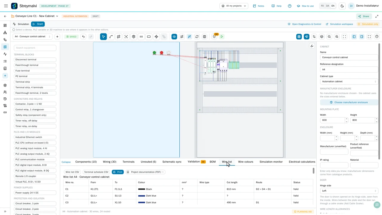
About this clip. It opens on the real Wire list tab. The printed sheets carry real captured content (schematic sheets, cabinet layout, wire list, terminal schedule, BOM, thermal results, PLC ladder and project check). The A4 page frame around some of them is a reconstruction, because the Documentation Builder's PDF output was not captured.
And there is more
Everything around the seven chapters
Further capabilities of the current development build (v0.27.6) that do not have their own chapter.
-
Component libraries
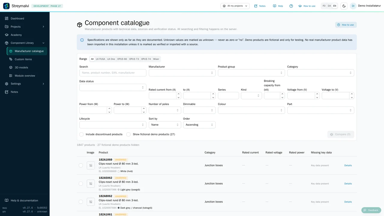
A manufacturer catalogue of genuine products, including Fibox ARCA enclosures, Schneider Altivar drives, Modicon M221 controllers, LK and Wiser fixtures, with sourced facts. Unknown values stay unknown.
-
Terminal block design
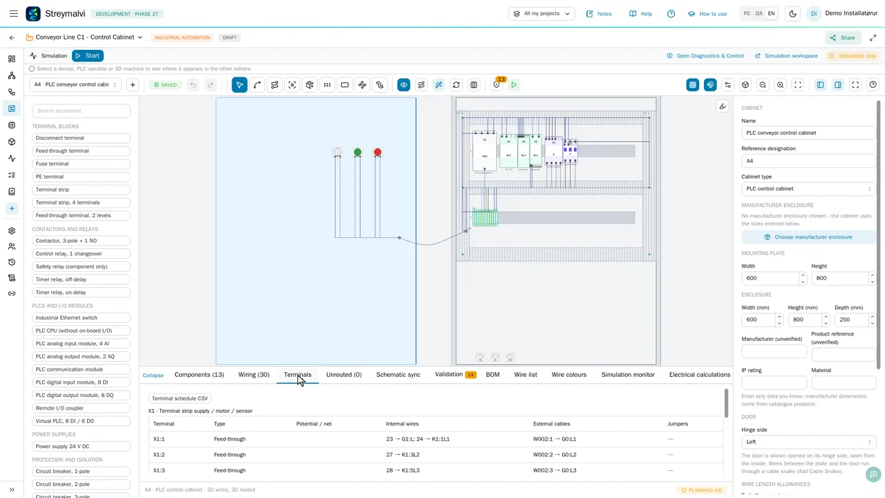
Feed-through, PE, disconnect, fuse and multi-level strips, Phoenix assemblies with bridges checked against potentials, numbering schemes and a terminal schedule.
-
More PLC languages
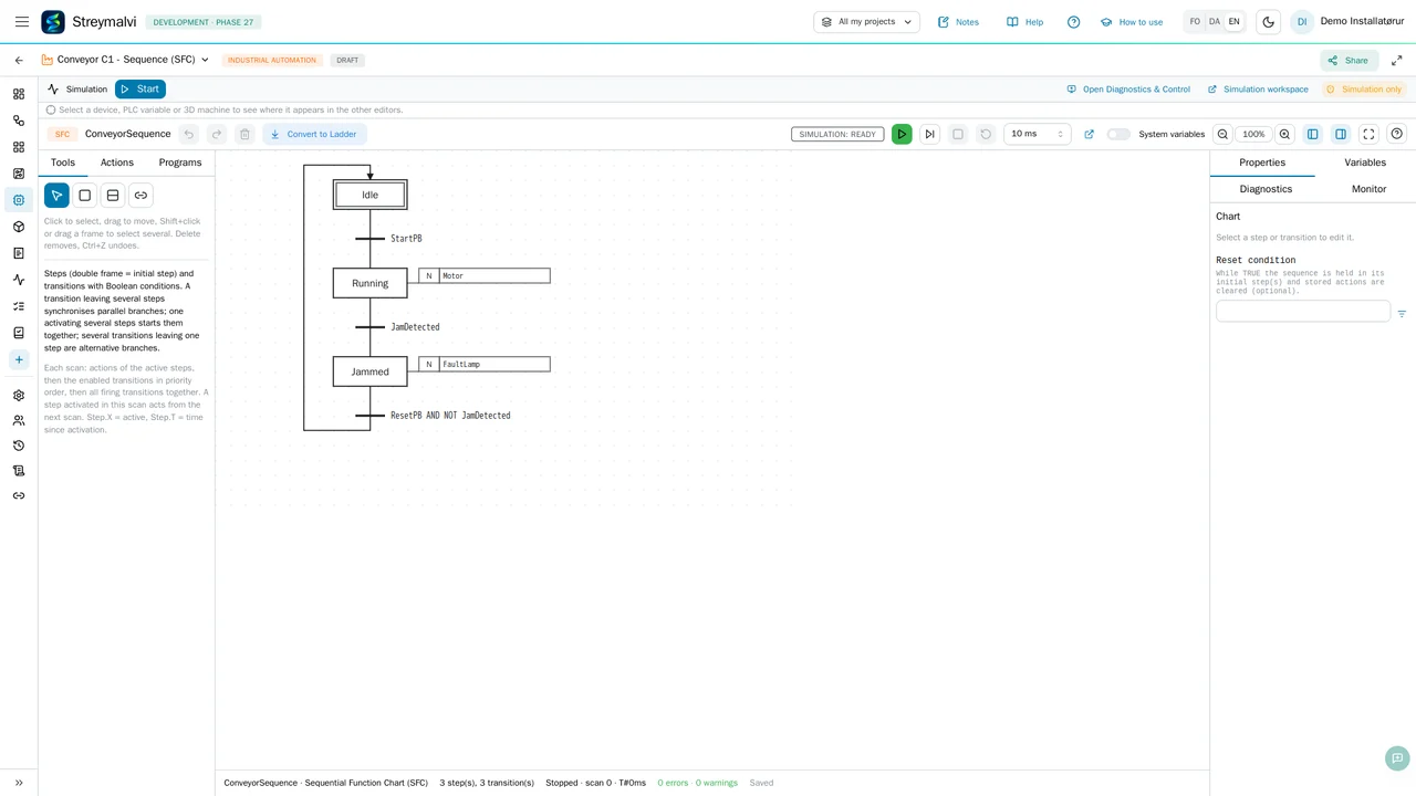
Function Block Diagram, Structured Text and SFC / GRAFCET-style charts next to Ladder, with timers, counters, PID and live highlighting of active steps.
-
Project Check
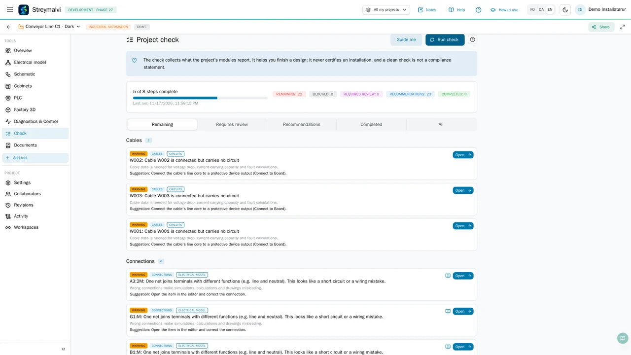
Automated checks against 33 Faroese and 31 Danish rules within their scope. Results guide the designer; they are never a certification.
-
Academy and tutorials
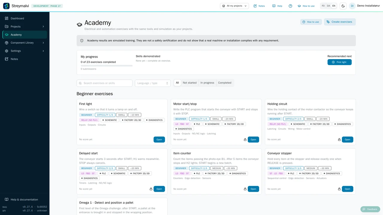
Exercises from first light to troubleshooting, assessed by the same simulation engine, plus step-by-step tutorials inside the real editors. Explore Education →
-
Factory simulation
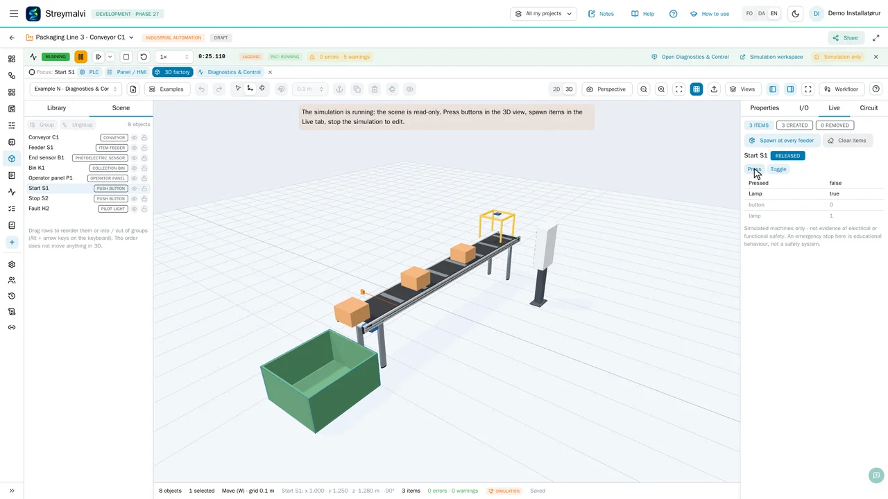
A 3D factory editor with 48 component types: conveyors, diverters, stop gates, transfer units, tanks and forklifts, plus seeded fault training and a first-person workfloor.
- Work orders issued from the Documentation Builder
- Distribution boards with circuit schedule, labels and a 3D view
- Operator panels and HMIs linked to PLC tags
- Lighting design with lux calculation and report
- Smart controls: simulated KNX, DALI and Wiser commissioning
- Help Center with about 108 articles in Faroese, Danish and English
- Examples library with read-only viewing and selective import
- Recording and replay of simulations, and thermal replay of recorded usage
- Guided measurements: a phone survey wizard for on-site measuring in development

From Design to Reality
Coming soon.
Streymalvi is in development and not publicly released yet. Everything on this page is shown from the current development build.